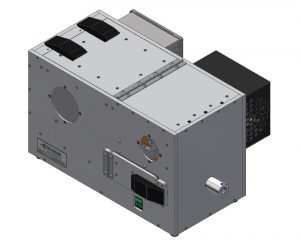
- Paddle wheel for increased operational capacity
- Feed outlet at lower position for heavier springs
- 1 outlet, standard
- Spring diameter (min/max): 0.250″ – 0.875″ (6.35mm – 22.2mm)
- Spring length: 1.50″ (38.1mm), max.
- Spring wire diameter (min/max): 0.025″ – 0.060″ (0.64mm – 1.52mm)
- Parts per minute: 25 max.†(varies according to spring size)
- Hopper capacity: 0.5 qt (0.5 ltr) – varies, depending on spring configuration
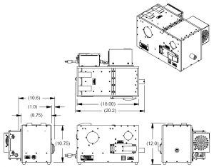
- Dimensions: 18″ L x 13.8″ W x 11.8″ H (457mm L x 350.5mm W
x 300mm H)
Required for operation (customer supplies):
- 115 VAC, 1A, 60 Hz power (230 VAC, 1A, 50 Hz optional)
- Air pressure: clean, filtered 90 psi (6.21 bar)
- *Air volume: The air supply flow rate needs to be at least 19 Standard Cubic Feet per Minute (SCFM) = .538 cubic meters per minute (m³/min)(8.97 liters/sec.).Note: Air consumption requirements may vary ±3 SCFM (±0.085 m³/min), depending on feeder configuration.
- Air supply line diameter: .275” (7.0mm) ID x .375” (9.53mm) OD
* Note: If sensors are added to the system control, to turn the feeder ON/OFF, (based on spring demand in tubing between feeder and escapement), the feeder must run a minimum time period of 1-2 minutes at a time. This is necessary to ensure the spring circulation and Blowback Feature (located in outlet nozzle) are functioning as designed. Additionally, the feeder needs to be running to have airflow down the tubing to the escapement to deliver springs at the required spring feed rate. (Parts per minute) If a sensor is located on the tubing, between the feeder and escapement, it should be located as close to the feeder nozzle exit as possible. This will maximize the queue of springs in the 2-3 feet of tubing prior to the escapement.

